
使用球形标定对增材制造的铝硅合金进行 EBSD 表征
导言
铝硅合金由于其高比强度、良好的耐腐蚀性和高耐磨性而常用于汽车和航空航天应用。通过增材制造生产这些合金具有额外的优势,包括与传统铸造材料相比更出色的机械性能、减少热裂纹以及创建定制和复杂设计的能力。在这些合金中添加硅有助于改善这些性能,但也会增加脆性。为了优化这些合金的性能,必须表征和了解由于合金成分以及所使用的增材制造工艺和参数而形成的微观结构。
讨论
电子背散射衍射 (EBSD) 是一种常用且功能强大的工具,可用于分析增材制造的晶体材料。然而,铝硅合金对传统的 EBSD 分析提出了挑战。这些合金中存在的初级相是 α 铝相和纯硅相。铝相是面心立方 (FCC)结构,而硅相是金刚石立方结构。在 FCC 相中,原子位于晶胞的顶角和各侧面中心。金刚石立方晶体结构基于面心布拉维晶格,每基元中包含两个原子。铝和硅的晶胞如图 1 所示。

这些晶体结构的相似性导致了其具有相似的 EBSD 花样,如图 2 所示,显示了使用运动学衍射模型模拟的铝和硅的 EBSD 花样。这些模拟花样显示了最高强度的衍射条带,这与传统 EBSD 花样标定中使用的霍夫变换图像处理中最有可能检测到的衍射条带相对应。由于两相具有共同的 FCC 结构,因此有许多共同的衍射条带。如果这些共同的衍射条带是检测并用于标定的条带,那么单独用 EBSD 就很难可靠地区分铝相和硅相,如图 3 所示。

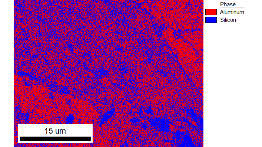
Figure 3. EBSD phase map using traditional Hough-based indexing for aluminum-silicon additively manufactured alloy. The speckled distribution of both phases shows the difficulty with this phase differentiation.
球形标定,一种新的EBSD 花样标定的强大算法,可以解决这个问题。球形标定在 EDAX OIM Analysis™软件的可选 EDAX® OIM Matrix™ 模块中使用。对于球形标定,将实验采集的每个 EBSD 花样与每个候选相(在本例中为铝和硅)的模拟主花样进行比较,并为确定的相和取向选择最佳匹配结果。这种方法使用实验花样中的所有信息,并且对这两相之间的花样差异更敏感。图 4 显示了铝相和硅相的代表性实验 EBSD 花样,以及相应的铝相和硅相对应取向模拟花样。动态衍射模型用于这些模拟,以创建用于球形标定的模拟主花样。比较模拟结果,硅花样中的其他条带是可见的,但强度较弱,因此使用传统标定的霍夫变换对这些条带进行检测的可能性较小。
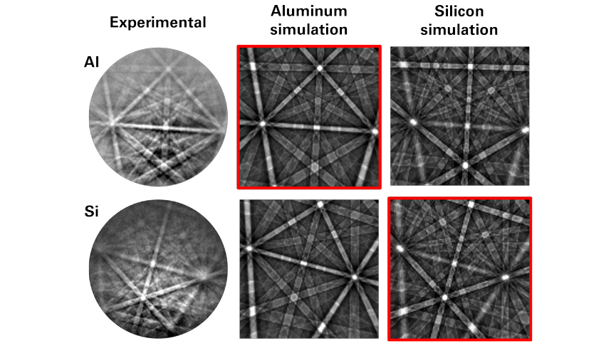
Figure 4. Experimental EBSD patterns from the aluminum and silicon phases, with dynamical diffraction simulations for both phases for the corresponding orientation. The selected phase is highlighted in red.

相比之下,使用球形标定方法(利用花样中的所有信息进行标定)可以提高对这些细微差异的灵敏度并提高相的区分度,如图 5 所示。
为什么正确分相很重要?单个 FCC 晶胞模型就可用于正确确定两相的取向。然而,如果研究人员想更深入地了解微观结构,那么能够分离铝相和硅相并分别分析这两个相就非常重要。图 6 显示了一个例子,其中显示了铝相和硅相的晶界取向差分布,以及组合分布(即所有数据取向差)。这种分布表明在 60° 取向偏差处有一个显著的峰值,这主要存在于硅相中。这是一个重要的取向差,因为它对应于材料中的孪晶,是具有潜在有益特性的晶界。通过球形标定正确区分两相,可以表征两相的晶粒尺寸、相占比、取向分布和晶界特征。此信息可用于优化增材制造参数并优化最终的性能。
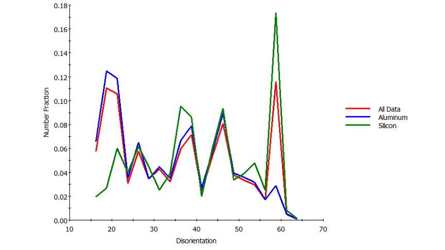
Figure 6. Disorientation distributions for the aluminum and silicon phases, and both phases combined (termed All Data).
结论
与传统的霍夫标定相比,球形标定提高了标定率和相区分性能。这允许准确表征相分布和微观结构信息,包括晶体取向、晶界特性和晶粒尺寸,这对于优化增材制造工艺参数和最终材料特性非常关键。